How To Read An HVAC Wiring Diagram
When I started in the HVAC trade, an HVAC wiring diagram looked like a different language to me because they were.
Not only were they a different form of communication, but every HVAC equipment manufacturer had their own way of drawing them out.
This was sometimes confusing, as each manufacturer’s rendition was like a different dialect or accent of the same language.
I hope that analogy hits home with you because that’s exactly how I felt, and if you’re currently learning wiring diagrams, I’ve been there and have felt your frustration.
If we break it down to the most basic level, wiring diagrams are made up of images that tell a story; that story includes things like order of operation as it pertains to the flow of power, images of parts like fans, relays, and compressors, power source, and all the interconnecting parts and wiring to complete them.
They also contain legends to quickly identify the parts within the drawing.
If you can understand HVAC wiring diagrams and understand them well, you can take your troubleshooting to the next level.
This is my first ever podcast episode, and it was on basic electrical; forgive me as I was learning the podcast ropes.
Main Parts
Let’s focus our attention on the main parts of a basic wiring diagram.
- Power Supply
- Switches
- Loads
Power Supply
The power supply is the power source that feeds the circuit; the loads within a circuit are rated for a certain voltage, amperage, etc.
The nameplate on the load will specify the information.
For instance, if the load is rated for 208 VAC, then the power supply serving that load must match or be within its limits.
If the source is below or above the nameplate rating, the load will not perform correctly, or it can cause damage or failure to the load itself.
✅ Hint, a load is like a motor or a compressor, but we’ll touch on that later.
A power supply could come from batteries, a transformer, or a main electrical panel in a home or building.
Switches
Switches are simple devices that open and close due to an action.
That action could be as simple as manually opening or closing the switch or a little more complicated, like switching in an automated process.
Switches can break an electrical circuit or provide power flow through them; switches are also rated for a maximum power supply that shouldn’t be exceeded when power is applied.
An open switch is a switch that does not allow power to flow from one side to the other.
A closed switch allows that same power to flow through it.
You may hear the term “contacts” when experienced professionals discuss switches.
This simply means that the switch parts are coming into contact or breaking contact to make or break a circuit.
Examples of Switches
- High/Low Pressure Switch
- Relay/Contactor Contacts
- Flow Switch
- Pressure Switch
An example of a switch changing position in an automated process would be: if a boiler pump were to start and create flow through a system, an inline flow switch would recognize this and change the switch’s position from open to closed due to water flow passing by.
Loads
Loads usually sit at the end of a circuit; after power moves from the power supply through an inline switch or switches, the load or loads are powered up and begin functioning.
Loads include motors, compressors, contactors, relay coils, and light bulbs.
Loads perform work and draw amperage.
This basic wiring diagram includes all three main parts, power supply, switch, and load.

Learning to Read Wiring Diagrams
We need to understand wiring diagrams and the main components and their differences.
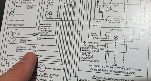
I remember pulling panels off HVAC systems, air conditioners, or a heat pump system as an apprentice, putting my finger on the power source, and following the diagram until I came across a component, usually a switch or a load.
I would then glance at the diagram legend to explain what my finger had stopped on.
I would then follow the diagram until the end.
I sometimes called tech support if I had trouble understanding a component’s functionality before moving on.
Repeating this process diagram after diagram was definitely my key to success over the course of time in understanding electrical drawings and interpreting their meaning.
Check out this training video on how to read wiring diagrams and schematic diagrams, and subscribe to the channel.