🔥 Flame Rectification Explained
A jittery pilot flame sits in a damp, poorly lit room.
The only source of light is a low-hanging fixture swaying back and forth due to a noisy ventilation system pulling in air from a filthy return air grill.
The room smells of cigarette smoke, stale coffee, and deceit.
In walks a gruff-looking character who appears to be visibly upset with the situation.
“So,” he says….” I heard you have been running your mouth again, telling all the good HVACers of the world that you are solely responsible for creating the signal required to prove flame in the heating cycle????”.
The flame develops a facade of anger and blurts out, “You can’t prove a thing. Go eat another donut pig!”
“Okay, have it your way…Hey Sarge, bring up the hose, would yah!”
🔥 The Misconception
There is a misconception out there that the flame itself generates the signal needed to prove flame and energize the “main valve” of the gas valve.
The flame does play an integral role but does not actually generate the signal, and it merely changes an AC current to a DC current through the process of flame rectification.
Back when I was in class for Gas Tech 1 training, my instructor used to repeat often that the ground reference used for flame rectification must be, at minimum, ten times greater than the flame sensor itself in order for the process to work.
I’m not sure how scientific that number is, but in general terms, it does play a significant role.
🔥 Process of Flame Rectification
Let’s look at the process of flame rectification as it relates to gas-fired appliances.
On a call for heat, providing that all safety switches and interlocks are in the correct position, the ignition control will receive power.
The controller will then send a spark to the burner assembly and energize the gas valve (pilot valve), you feel me?
Upon ignition, the flame will generate a DC micro amp signal and send it back to the ignition control….Wrong, well, kind of.
Before we continue, we must understand that the flame, in this case, acts as a conductor, just like a wire.
How does this happen?
Within the flame, there are free-moving ions, the ions in the flame allow current to pass through the flame just like current passes through a wire.
So let’s rewind…
After the spark has been created, the ignition control sends an AC voltage to the flame sensor, usually less than 100 volts.
That voltage passes through the flame and makes its way to the ground.
This is where the ten-to-one ground reference thought comes into play.
The burners, providing they are grounded properly, have a much larger surface area than the flame sensor.
Due to this size difference, the current moves in one direction toward the grounded burners.
During this process, there is a small pulsating DC – offset current that results (in flame rectification).
That small DC current, also known as microamps, is what the ignition control uses to verify the flame is present.
If the flame drops out, the path to ground disappears, and so does the micro amp signal.
🔥 Rectification – The process in which AC current is converted to DC current.
🔥 Flame Failures
Most all flame failure issues have nothing to do with a faulty flame sensor. Remember, it’s just a wire.
Poor ground, loose connections, or faulty ignition control will most likely be your culprit.
Keep in mind that a dirty flame sensor will cause ignition failure issues and should be kept clean.
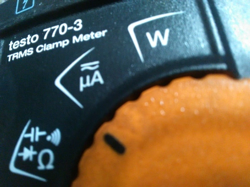
To check for a micro amp signal, you must use a meter that has a micro amp function.
It will be labeled uA on the meter selector switch, similar to the headline photo of the Testo 770-3.
Set your meter to microamps, attach one meter lead to the flame sensor and another meter lead to the flame sensor terminal on the ignition control so that your meter leads are connected in series with the circuit.
During ignition, the micro amp signal will be displayed on your meter screen.
The correct micro amp reading will differ depending on the manufacturer, and I strongly suggest you contact them for the correct information.
Check out this quick video on how to check a flame signal
For further explanation, check out instructor12b’s YouTube video below and subscribe to his channel…
So to quickly recap, the ignition control board will provide an AC voltage to the flame sensor, the flame will become a conductor allowing current to flow in the direction of the burners.
During the process, the result is a pulsating DC – offset current (micro amps), which can be read with a meter connected in series with the circuit.
This process is known as flame rectification.
Keep your flame sensors clean and burners properly grounded.
🔥 Finally
Check out the link to my YouTube channel for more tips, tricks, and troubleshooting videos, and check out The HVAC Know It All podcast here or on your favorite podcast app.